Saturday, June 18, 2011

Piston ring sets and piston pins

The engines of most passenger cars and light commercial vehicles have pistons with a set of three rings. Typical ring sets are shown in Figures 6.18 and 6.20. There are various combinations of compression rings and oil rings. Usually, there is a top compression ring, a scraper ring, and a segmental oil ring.
Piston-ring coatings
Some piston rings are coated with a soft material to assist them to ‘bed in’. New rings and cylinders have very small irregularities and when these wear off, the rings will provide a better seal. To assist this process, the rings can be coated with phosphate, graphite or iron oxide. These are relatively soft substances which wear more quickly than the ring material. The coatings also absorb oil and help with ring lubrication. This prevents scuffing of the cylinder walls.
To prevent wear, the face of the piston ring can be coated with chromium. This is a relatively hard material, but it operates well against the cast-iron cylinder walls without scuffing.
Molybdenum is also used as a coating for compression rings. It has properties that give quick bedding-in. Rings coated with molybdenum resist abrasive wear much better than uncoated cast iron rings, but not as well as chromium-plated rings.

Fig 6.21
Piston pins
The piston pin secures the piston to the small end of the connecting rod and also provides the wrist-like action that is needed between the two parts.
There are different methods used to retain the piston pin, but two that are commonly used are shown in Figure
6.21. These are:
1. Press fit pin. The piston pin is a press fit in the eye of the connecting rod and floats in the piston. The fit in the connecting rod is tight enough to retain the pin and prevent it from moving. This is the method most commonly used for engines in passenger cars and light commercial vehicles.
2. Floating pin. The piston pin is arranged to float in both the eye of the connecting rod and the piston. Circlips in grooves in the piston bosses retain the piston pin and prevent it from coming into contact with the cylinder walls.
There are variations of the designs shown. With some floating piston pins, thrust pads of soft metal are fitted in the ends of the pins. The pin floats in the piston and in the connecting rod. The thrust pads are allowed to come into contact with the cylinder wall, but being soft and lightly loaded, they do no hanu.
With another design, the piston pin is clamped in the connecting rod. The eye of the rod is split and a bolt is used to form it into a clamp. This design increases the mass at the small end of the connecting rod, which is not desirable because it adds to the mass of the reciprocating parts.


·              The piston pin is also referred to as a wrist pin, and sometimes as a gudgeon pin.

Fig 6.22
Piston-pin lubrication
Most piston pins depend on splash and oil mist for lubrication, but some piston pins are pressure- lubricated. For this, an oil passage is drilled the full length of the connecting rod. Oil from the connecting- rod bearing passes through the passage to the piston pin.
Most engines have a connecting rod with a ‘spit hole’, or oil jet, in the crank-pin end. This hole lines up with the oil hole in the crank-pin once on each revolution of the crankshaft. When this occurs, a squirt of oil is directed onto the cylinder walls as shown in Figure 6.22. This also lubricates the piston pin.
In engines with piston cooling jets, the oil directed from the jet cools the piston and also lubricates the piston pin (previous Figure 6.9).

Continued
See Connecting rods>>>>>>>>>>>>>>>>>>

Friday, June 17, 2011

Piston rings

There are two general types of piston rings: compression rings and oil rings. They fit accurately into the grooves in the pistons. Compression rings provide a gas seal against the cylinder walls, while oil rings control the oil on the cylinder walls and return excess oil to the oil pan.

·           Oil rings are also referred to as oil-control rings.

Fig 6.13
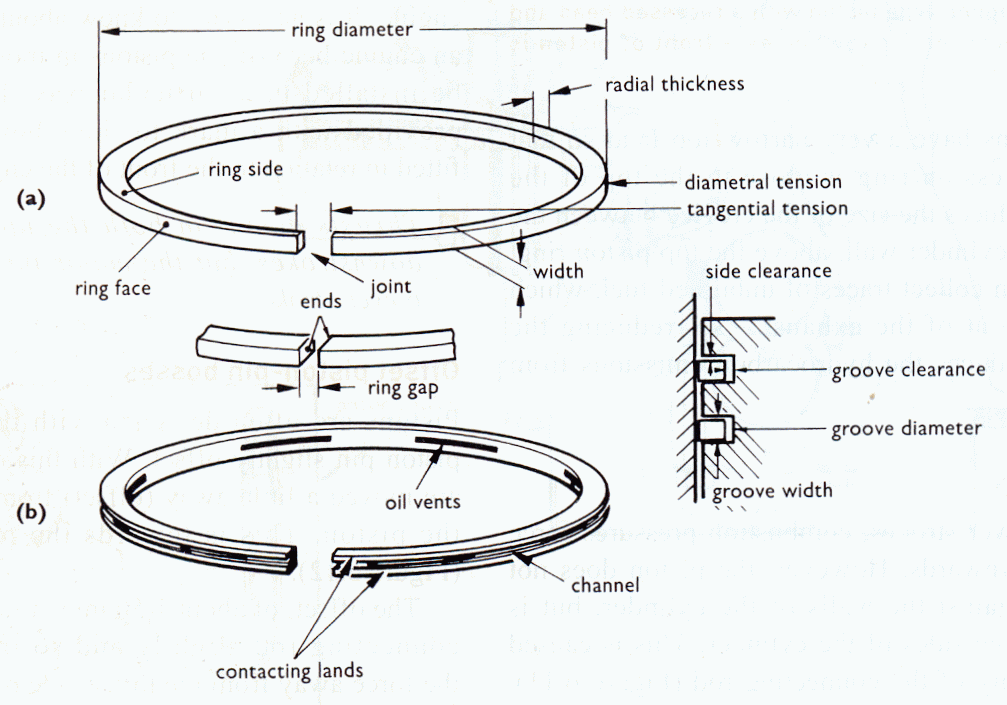
Figure 6.13 shows a basic compression ring and a basic oil ring with their parts named, but there are a number of variations in design. Piston rings are split so that they expand against the cylinder walls. This also enables them to be fitted into the grooves in the piston.
When removed from the engine, piston rings are larger in diameter than the cylinder, but when installed, they are compressed so that the gap is almost closed. The tension within the rings keeps them against the cylinder walls.

Fig 6.14
Compression rings
Compression rings have to provide a seal that prevents loss of air during the compression stroke and loss of gas pressure during the power stroke. If the rings do not seal properly on the compression stroke there will be loss of compression and engine power. If the rings do not seal properly during the power stroke then combustion gases will be forced past the piston into the crankcase. This condition occurs in a worn engine and is known as blowby.

Types of compression rings
Figure 6.14 shows the shape of the cross-section of a number of compression rings. They all depend on the tension within the ring to hold them outwards against the cylinder walls, but
some have features that provide additional pressure in operation. Some have a torsional action.
1. Tapered ring has a slightly tapered face that helps to scrape oil from the cylinder walls.
2. Chamfered ring the chamfer on the back of the ring produces an increased pressure against the cylinder walls.
3. Counter-bored ring a back edge of the ring is cut away to give a torsional action.
4. Undercut ring the face is slightly tapered and its lower part cut away to give a torsional
Fig 6.15 (a & b)
action.
5. Plain ring has a rectangular section and is held against the cylinder wall by its own tension.
6. Faced ring the facing resists heat and wear.


Torsional rings
Figure 6.15 shows the torsional action of compression rings with shaped cross-sections. This is shown on both the intake stroke and the power stroke.
During the intake stroke, internal forces in the ring (due to removing a corner of the ring) cause the ring to twist slightly (Figure 6.15(a)). As the piston moves down the cylinder, the rings have a scraping action that removes surplus oil from the cylinder walls. On the piston
Fig 6.16
upstrokes, the rings tend to slide over the film of oil and so have less tendency to carry oil up into the combustion chamber. 

During the power stroke (Figure 6.15(b)) combustion pressure forces down on the top of the ring and also against the back of the ring. This straightens the ring so that it has fill-face contact with the cylinder walls. This provides effective sealing.
Because of their twisting action, rings with a chamfer or counter-bore that act in the way described, are known as torsional rings. Figure 6.16 shows how gas pressure from combustion gets behind the ring to force it against the cylinder wall and also downwards against the piston.
Where shaped rings are used, the top of the ring is marked in some way so that it can be installed correctly (Figure 6.17).
Fig 6.17

Oil rings
Oil-control rings prevent excessive oil from working up past the piston into the combustion chambers. The oil that has to be controlled is thrown from the connecting-rod bearings and, in some cases, from an oil jet, or from an oil-spit hole in the connecting rod (Figure 6.22). Generally, there is more oil than needed on the cylinder wall and the oil rings remove the surplus. They also help to provide a seal.

Types of oil rings
The oil ring in Figure 6.13(b) is a one-piece ring that depends on its own tension to hold it
Fig 6.18
against the cylinder walls. The slots in the ring, and the holes in the piston behind the ring, allow oil to return to the oil pan. This type of oil ring is usually used only in conjunction with another oil ring.
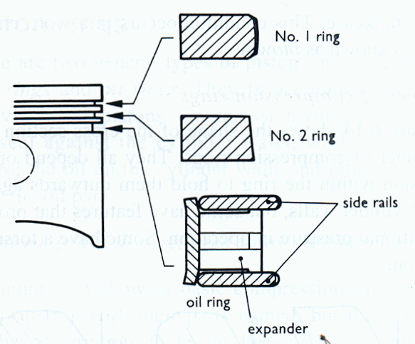
Most oil rings are segmental types with three or four segments, like the oil ring in Figure 6.18. This ring has two side rails and an expander, which also acts as a spacer for the rails.
The side rails are usually of steel, with very little tension of their own. They depend on the expander to hold them against the cylinder walls. The expander is made of spring steel with a series of crimps which give it an outward spring force.
Fig 6.19
·       This type of oil ring is very flexible and its open construction allows oil to pass through readily.
 
Oil control
Under most circumstances, there is far more oil on the cylinder walls than is needed for lubrication, but the oil does several things: it lubricates, cools, cleans and seals. Most of the oil that is not needed for lubrication is scraped off the cylinder walls by the oil rings.
Fig 6.22
Figure 6.19 shows how oil can be controlled. As well as drain slots behind the oil ring, this piston has grooves which allow oil to pass down the sides. Oil scraped by the oil ring is returned to the oil pan through the spaces at the end of the piston-pin bosses and through the grooves provided in the sides of the piston. 


Continued
See piston ring sets>>>>>>>>>>>>>>>>>>>>>>>>>>>>

Thursday, June 16, 2011

Piston designs

Fig 6.10
Pistons are designed with various shapes. The head of the piston can be flat, domed or hollow. The piston can have a short skirt, a full skirt, or the skirt can be cut away.
The shape of the piston head is designed to suit the type of combustion chamber of the engine and to improve turbulence of the air as it is being compressed. The head of the piston can also be designed with recesses or depressions to provide clearance for the heads of the valves.
Petrol engines use a slipper-type piston (Figure 6.10). Cutting away the skirt of the piston not only reduces the mass of the piston, but also provides clearance for the crankshaft balance weights when the piston is at BDC. This enables shorter connecting rods to be used, permitting a more compact engine design. On some engines, the balance weights are contoured to avoid interference between the weights and the pistons.
Some pistons have a very narrow top land so that the top compression ring is close to the top of the piston. This reduces the size of the crevice between the piston and the cylinder wall, above the top piston ring. The crevice can collect traces of unburned fuel, which finds its way out of the exhaust so, reducing the crevice size reduces the hydrocarbon emissions from the engine.

Piston thrusts
Fig 6.11
During the power strokes, combustion pressures force the piston downwards. However, the piston does not bear evenly against the walls of the cylinder, but is thrust against the sides of the cylinder. This is caused by the angularity of the connecting rod (Figure 6.11).
The combustion pressures force the piston downwards, and the connecting rod offers resistance, but it does this at an angle. The result is a side thrust of the piston against the cylinder wall, as shown.
The piston also has a side thrust during the compression stroke, but this is on the opposite side of the cylinder. Also, this is a lesser thrust because the downward force from compression is much less than the downward force of combustion.
The thrusts are sometimes referred to as the major and minor thrusts. Because the thrust during the power stroke (major thrust) is most important, this side of the engine is often referred to as the thrust side of the engine. It is necessary to know about the thrust side of an engine because the pistons in most engines have to be installed in a particular way. Pistons are often provided with a mark to show how they should be fitted in relation to the front of the engine.


·      Thrusts occur on both the upstrokes and the down-strokes, but the major thrust is 
during the power stroke.


Fig 6.12
Offset piston-pin bosses
Pistons are often designed with the bosses for the piston pin slightly offset. With this design, the bosses are moved a little away (offset) from the centreline of the piston. This is towards the major thrust side (Figure 6.12).
The offset, of about 1.50 mm, alters the angle of the connecting rod slightly and so transfers some of the force away from the thrust side of the piston. There is less tilt applied to the piston during the power stroke and so there is less chance of piston slap.
Offset pistons must be installed the correct way, otherwise the tilting action would be increased and this would cause pronounced piston knock. The front of the pistons will be marked for correct installation.


Continued
See piston rings>>>>>>>>>>>>>>>>>>>>
Wednesday, June 15, 2011

Pistons, connecting rods and bearings

Fig 6.1
Pistons are designed to resist high combustion temperatures and their piston rings have to seal against high combustion pressures. Connecting rods have to withstand high stresses as they transfer the reciprocating motion of the pistons to the cranks of the crankshaft.
The piston, piston rings, piston pin, connecting rod and the bearing form the piston and connecting- rod assembly. The various parts are identified in Figure 6.1
.

Pistons
Figure 6.2 shows a piston with its parts identified. This is a short-skirt piston with grooves for three piston rings. There are a number of variations in piston design, which include shape, mass, provision for expansion, and type of material.
Pistons are made of cast iron or aluminium alloy. Aluminium alloy pistons are used in petrol and smaller diesel engines because they arc much lighter than cast iron pistons. However, aluminium has a greater rate of expansion than the cast iron cylinders in which most pistons operate. Because of this, aluminium alloy pistons are specially designed to control expansion. Some larger diesel engines, which operate at lower rpm than petrol engines, have cast iron pistons.
Fig 6.2

Piston clearance
A piston is slightly smaller in diameter than the cylinder in which it operates. This gives it a working clearance of about 0.02 mm to 0.05 mm. Figure 6.3 illustrates the clearance of a piston in its bore, but there are particular ways in which it is measured.

·       See Figures 7. 7 to 7.9 in the coming posts which show how piston clearance is measured.

If a piston has insufficient clearance, there will be no room for the piston to expand when it is hot and it will tend to seize on the cylinder wall. This would cap score both the piston and the cylinder. If there is too much clearance, piston slap will occur, particularly when the engine is cold. Piston slap is caused by the sudden tilting of the piston in the cylinder as it starts down its power stroke. This is done with such force that it produces a distinct noise.
Fig 6.3

·     Piston slap can occur in older engines that have excessive piston clearance due to worn cylinders or worn or collapsed piston skirts.

Piston temperature
The piston is subjected to the full effects of combustion and so it has to be resistant to heat. Typical operating temperatures are shown in Figure 6.4. Under heavy operating conditions, these temperatures can become even higher.
There is a big difference between the temperature of the head of the piston and the skirt of the piston. The heat causes expansion, and this is greatest at the top of the piston. For this reason, the lands at the top of the piston are given extra clearance. They could be as much as 0.75 mm smaller in diameter than the skirt.
Fig 6.4

Control of piston temperature
There are several methods used to prevent pistons from expanding excessively. These include cam grinding, using steel struts, controlling the heat path, and oil cooling. All pistons have some means of controlling their temperature and some pistons have more than one.

Fig 6.5
Cam-ground pistons
A piston that is cam-ground is slightly oval in shape. The shape is obtained by relieving some metal in the area of the piston-pin bosses (Figure 6.5). This makes the diameter of the piston slightly smaller at the piston- pin bosses than at the thrust faces. This allows the piston to be fitted to the cylinder with minimum clearance at the thrust sides. The extra clearance provided at the bosses by cam grinding allows for piston expansion.


·    For an explanation of piston thrusts, see the coming post ‘Piston thrusts’.

Cam-ground pistons get their name from the process by which pistons were finished to size. The machine uses a cam to move the piston backwards and forwards as it is being ground. When cam-ground pistons warm up, they become more round in shape, so the area of contact with the cylinder wall increases (Figure 6.6). Grinding generally refers to cast iron pistons, aluminium pistons can be turned, rather than ground.
Fig 6.6

Steel-strut pistons
Special alloy-steel struts are cast into the piston during manufacture. A strut is fitted to each side of thc piston (Figure 6.7). The steel from which the struts are made has a very low rate of expansion when it is heated. On the other hand, aluminium alloy has a fairly high rate of expansion. As the temperature of the piston increases, the aluminium alloy tries to expand, but it is restrained by the steel struts. This holds the piston at the thrust face to its specified size.
Fig 6.7

Heat path in pistons
As well as controlling piston expansion by struts, heat is kept away from the thrust faces of the piston as much as possible. This also reduces expansion.
One way of doing this is with horizontal slots in the thrust sides of the piston, either in or below the oil-ring groove (Figure 6.8). The slots are used to break the heat path between the head of the piston and the skirt at the thrust faces. The heat is directed to other parts of the piston, such as the piston-pin bosses, where there is more clearance and also more metal to absorb the heat. This reduces expansion at the thrust faces.
Fig 6.8

Piston cooling jets
Normal lubrication helps to cool the pistons and cylinder walls, but as well as this, some engines have cooling jets. These are small nozzles, or jets, which spray a jet of oil up into the piston. The oil strikes the piston head, absorbs heat and then drops back into the oil pan. The oil also lubricates the piston pin and cylinder walls.
Figure 6.9 shows a cooling jet and its action. The jet is supplied with oil from the main oil gallery of the engine. It has a ball cheek valve that closes when the oil pressure in the gallery is low, or when the engine is stopped. At normal operating pressure, the ball valve is forced off its seat, so that the jet sprays oil into the piston. 
Fig 6.9


 Continued
See piston designs>>>>>>>>>>>>>>>>>

Tuesday, June 14, 2011

Analyzing bearing failures


Fig 5.32 (a-c)

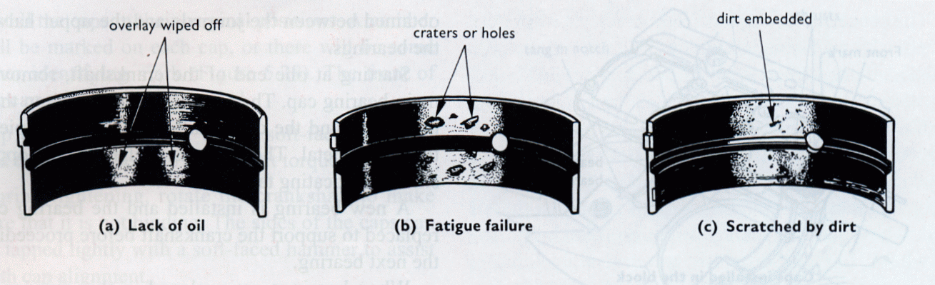
Figure 5.32 shows a number of ways in which engine bearings can fail. Generally, these apply to both main bearings and connecting-rod bearings, but some conditions are more likely to occur with connecting- rod bearings.
When analyzing a bearing failure, consider the conditions under which the bearing operates and the loads that the bearing has to carry. This will help to find the cause of the problem.

Lack of oil
Refer to Figure 5.32(a). A bearing that is short of oil will overheat and bearing metal will be wiped off the steel back. If the bearing has no oil supply, almost all the bearing metal will melt. The steel back will then run directly on the journal and this will damage the journal. The crankshaft will have to be replaced, or the journals ground undersize.
Lack of oil can be due to clogged oil lines, a defective oil pump, a faulty relief valve, or insufficient oil in the oil pan.

Fig 5.32 (d-f)
Fatigue failure
Refer to Figure 5.32(b). Repeated application of loads on a bearing will fatigue the bearing metal so that it starts to crack. Small pieces break away from the steel back and small craters or holes form in the bearing. With continued use, more and more particles break away until a large surface of the steel back is exposed.
The bearing is designed to resist fatigue under normal operating conditions, but there are conditions that could cause this problem. One condition is an out- of-round journal, which stresses the bearing with every crankshaft revolution.
If the engine is lugged, the upper half of the connecting-rod bearing will be heavily loaded and could fatigue. High-speed operation could also cause fatigue, but this would be in the lower half of the bearing.

·         The terms lugged and lugging refer to operating the engine at low speed at full throttle.

Scratched by dirt
Refer to Figure 5.32(c). Some very small particles in the oil could become embedded in the bearing metal. Any larger particles will be carried around with the journal or bearing and will scratch the bearing surface.
The cause could be poor cleaning during repairs, contaminants introduced with the oil, or a faulty oil filter.

Tapered journaL
Refer to Figure 5.32(d). If a journal is tapered, one side of the bearing will carry most of the load. This side will overheat and lose its bearing metal.
This should not be confused with a failure from a bent connecting rod. With a tapered journal, both halves of the bearing will fail on the same side. With a bent connecting rod, the top half of the bearing will fail on one side and the bottom half will fail on the opposite side.

Radius ride
Refer to Figure 5.32(e). If the radius between the crankshaft journal and web is too large, the edge of the bearing will ride on the radius. There would be no clearance and metal could be wiped off the edge of the bearing. Also, the bearing could be cramped, causing poor seating, rapid fatigue and early failure.
This problem could occur after a crankshaft has been ground if the edges of the journals have not been given the correct radius.

Poor seating
Refer to Figure 5.32(f). Poor seating of a bearing in its bore will cause high spots where there is not enough bearing clearance. This will show up as bright sections where the bearing is worn.
Poor seating not only reduces bearing clearance and causes wear, but it leaves air space between the back of the bearing shell and its bore. This interferes with heat transfer from the bearing to its cap or to the crankcase. 

Continued
See pistons, connecting rods and bearings

Monday, June 13, 2011

Main bearings Service

Fig 5.22 measuring journal size


With an engine dismantled, the main bearings can be checked visually for wear or damage as outlined below (see later section Analyzing bearing failures’). The crankshaft-to-bearing clearance can be checked by measurement or with Plastigage.
Figure 5.22 shows how the clearance is found by measuring the crankshaft journal with a micrometer and the bearing      with a dial gauge. Readings are taken at four different places on the shall, and four measurements are made of the bearing. The dial gauge reading can he checked with the micrometer to determine the bearing clearance.
Fig 5.22

Using Plastigage
The use of Plastigage to check a bearing clearance is shown in Figure 5.23. The procedure is:
I. Wipe the journal and bearing clean of oil.
2. Place a strip of Plastigage in the centre of the bearing.
3. Replace and tighten the bearing cap and do not turn the crankshaft.                                                                                                 Measuring bearing dia.
4. Remove the cap and, with the scale provided, measure the flattened Plastigage at its widest point this is the bearing clearance.

·           For more information on Plastigage, refer to the section ‘Checking connecting-rod bearings’ in later
posts.
Fig 5.23
  
Conditions during measurement
If the engine is removed from the vehicle and upside down, then the crankshaft will rest in the bearings that are in the crankcase. The clearance will be between the journals and the halves of the bearings in the caps. This is where the Plastigage is used to take the measurements.
However, if the engine is installed in the vehicle, the crankshaft will rest in the bearings in the caps. Therefore, it must be held upwards to obtain the clearance and to prevent incorrect measurement.
One way of supporting the crankshaft is to place a small jack under the web of the crankshaft, next to the bearing being measured. Another method is to remove the bearing from the bearing caps on each side of the bearing that is to be measured and insert soft packing pieces. The cap bolts are then tightened to lift and support the crankshaft.

Checking crankshaft end-play
Fig 5.24
Crankshaft end-play will become excessive if the end- thrust bearings are worn. This can produce engine noise in the form of a noticeable sharp irregular knock.
Check the end-play by forcing the crankshaft endwise as far as it will go with a pry bar and then measuring the clearance at the end-thrust bearing with a feeler gauge (Figure 5.24). Consult the engine manufacturer’s manual for allowable end-play.

Replacing crankshaft rear oil seal
Fig 5.25
An oil seal is fitted at the rear main bearing to prevent oil leakage (Figure 5.25). When main-bearing service is being performed, or whenever leaking is noticed at the rear main bearing, the oil seal must be replaced.
The procedure for replacement varies with different constructions. On some engines using a split oil seal, the crankshaft must be removed and a special oil-seal installer used to insert the new seal in the cylinder block.
On engines with seals of the type shown in Figures 5.25 and 5.26, it is not necessary to remove the crankshaft. However, components have to be removed from the rear of the engine to gain access to the oil seal. These include the transmission, clutch and the flywheel. For an automatic transmission vehicle, the components would be the automatic transmission, the torque converter and its drive plate.
The rear oil seal in Figure 5.26 is a lip-type seal that fits into a housing. The housing is then bolted to the block.


Fig 5.26
·         The illustration shows a drive plate for the torque converter of an automatic transmission

Replacing main bearings
In most cases where main bearings are being replaced, the engine will have been removed from the vehicle and completely dismantled.
Bearings are installed as follows:
1. Wipe the bearing bores and the bearing caps clean.
Fig 5.27
2. Coat the upper halves of the bearing with engine oil and slide each bearing into its correct bore in the crankcase (Figure 5.27).
3. Make sure that each bearing is properly seated in its bore and that the tang of the bearing fits into the notch in the bore.
4. Oil the crankshaft and install it in the bearings in the crankcase.

5. Fit the lower halves of the bearings in their caps, making sure that they seat properly.
6. Install the caps in their original positions. A number will be marked on each cap, or there will be some other identifying mark (Figure 5.28). The front of the cap must also be identified.
7. Tap the caps into place with a soft-faced hammer and tighten the bolts to the correct torque.
8. During tightening, rotate the crankshaft to make sure that it is not binding. The sides of the caps can be tapped lightly with a soft-faced hammer to assist with cap alignment.
Where the thrusts are separate from the bearing (Figure 5.29), the bearing is installed in its bore. The thrusts are then installed in their grooves in the crankcase web beside the bearing.

 
Fig 5.28
·         All main bearings are not the same, some are grooved and one could have thrust faces.

Tightening bearing cap bolts
There are a number of designs of main-bearing caps where the cap bolts have to be tightened in a specified sequence. Figure 5.30 shows a sequence for main bearings that have a beam-type cap. The bearing caps are joined together to provide rigidity. The cap bolts must be tightened progressively in the right sequence as well as to the correct torque.
Figure 5.31 shows another crankshaft and bearing assembly. This has four bolts for each bearing cap and
a bearing cap bridge, or beam, that fits over the bearing caps. The cap bolts secure the bridge as well as the bearing caps. The sequence for tightening the bolts is shown. This starts with the two inner bolts of one bearing. It follows a spiral pattern, with the inner bolts being tightened before the outer ones.

Fig 5.29
·         All main bearings are not the same, some are grooved and one could have thrust faces.


In some engines, the main-bearing inserts can be removed and replaced with the engine in the vehicle. This is done without removing the crankshaft from the engine. This would only be done if the crankshaft journals were not worn or scored.
The method involves slackening off all the main- bearing cap bolts one or two turns so that clearance is obtained between the journals and the upper halves of the bearings.
Starting at one end of the crankshaft, remove the main-bearing cap. The upper bearing insert can then be pushed around the crankshaft journal using a piece of thin, soft metal. The insert
Fig 5.30
is pushed on the opposite side to its locating tang.
A new bearing is installed and the bearing cap is replaced to support the crankshaft before proceeding to the next bearing.
When bearings are replaced in this manner, it is essential that every care be taken in regard to cleanliness. Unfortunately, it is not possible to see how the new bearing is located in the housing once it has been installed, so that every care must be taken during assembly.


·      The preferred method of installing main bearings is with the engine completely dismantled and the crankshaft removed.

Fig 5.31
Bearing oil-leak test
Main bearings and connecting-rod bearings can be checked with a bearing leak tester. The oil pan has to be removed so that the amount of oil passing the bearings can be seen.
The tester is basically a pressure container of oil that is connected by a hose to the oil gallery of the engine. It uses compressed air to supply the stationary engine with oil at normal oil pressure.
A normal bearing will leak between about twenty to 150 drops of oil per minute. A bearing will leak more if it is worn or has excessive clearance. Less than twenty drops could mean a restricted passage or blocked oil-way.
If oil passages in the crankshaft and bearing happen to be in line, then more oil than normal will pass through the bearing. This could give the impression that the bearing has excessive clearance.


·         If this happen; the crankshaft should be turned to move the oil holes away from each
other.

Continued
See Analyzing bearing failures>>>>>>>